


Tutoriel d’utilisation de l’écran 4 afficheurs 7 segments I2C

Composants utilisés
- 1x Carte Arduino Uno
- 4x Câbles de branchement Dupont mâle / femelle
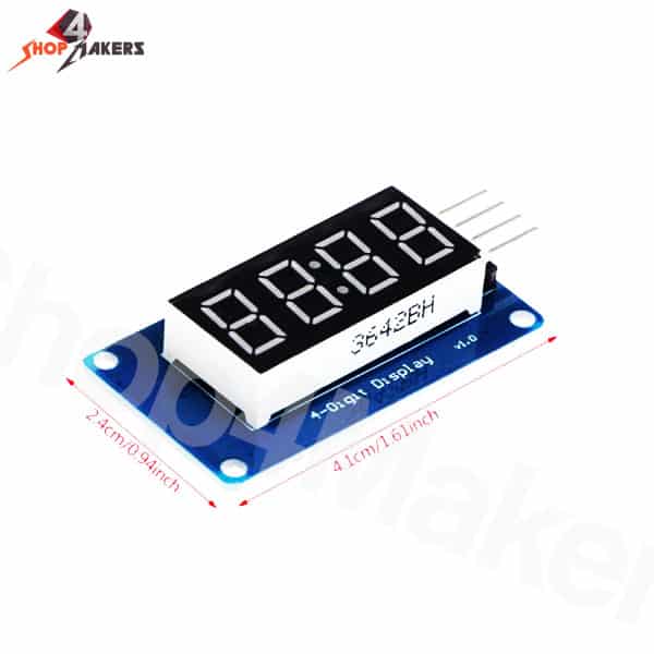
- 1x Ecran 4 chiffres 7 segments I2C avec driver IC TM1637
 .
.
Principe de fonctionnement
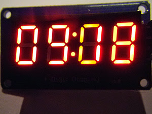
Cet écran à 4 afficheurs permet d’afficher des chiffres de 0000 à 9999, par exemple pour visualiser une vitesse, un score de match, un voltage de batterie, l’heure, un chronométrage.. etc. ou tout autre projet qui requiert un afficheur numérique.
De nombreuses applications sont possibles, la luminosité réglable de l’afficheur permettant aussi une lecture dans le noir.
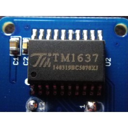
Son interface I2C n’utilise que 2 fils de l’Arduino ou du micro contrôleur (clock et data), au lieu d’une douzaine de fils et de pins utilisés, grâce au driver TM1637.
On peut régler l’intensité d’éclairage globale sur plusieurs niveaux (0-7).
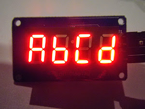
L’écran peut afficher les chiffres 0-9, et les lettres A-F (codées 10 à 15) ainsi qu’un double point central de séparation.
 .
.
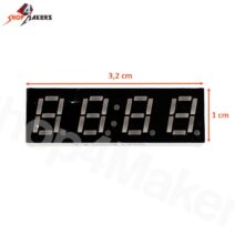
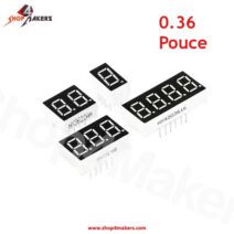
Le driver d’affichage et l’afficheur
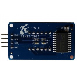
Câblage
Ecran 7 segments I2C –> Carte Arduino
- GND –> GND
- Vcc –> 5V
- CLK –> Scl pin A5
- DO -> Sda pin A4
Librairies
Télécharger les deux librairies DigitalTube et TimerOne (lien en bas de page)
Après décompression leurs dossiers doivent être renommés TimerOne (avec ses deux fichiersTimerOne.h et TimerOne.cpp) et DigitalTube.
Les déplacer dans votre répertoire …/librairies/
Relancer l’IDE d’Arduino pour finaliser l’installation.
Programmation
Exemple de code 1 : Horloge
à télécharger dans la carte Arduino
Cette horloge affiche le temps au format HH:MM ou MM:SS. Elle utilise une interruption qui met à jour 2 fois par seconde le temps.
Au démarrage l’écran affiche un exemple alphanumérique “abcd”.
 .
.
- CODE:
<code>//********************************************************#include <TimerOne.h>
// Afficheur 4 chiffres 7 segments
// avec Driver TM1637 et Arduino
// demo_7segment_i2c_clock
//
// Affiche une horloge 12:00 sous format hh:mm ou mm:ss
//
// tiptopboards modifié 15 11 2014
//********************************************************
// Source : Frankie.Chu 9 April,2012
#include “TM1637.h” //librairie du driver du 7 segments
#define ON 1
#define OFF 0
#define hhmm 01 //0 pour afficher HH:MM et 1 pour MM:SS<code>int8_t TimeDisp[] = {0x00,0x00,0x00,0x00}; //Tableau des 4 chiffres
unsigned char ClockPoint = 1;
unsigned char Update;
unsigned char halfsecond = 0;
unsigned char second;
unsigned char minute = 0;
unsigned char hour = 12; //Heure 12:00:00 pour initialiser<code>// branchement I2C sur CLK -> pinA5 et DIO –>Pin A4
#define CLK A5
#define DIO A4 //3
TM1637 tm1637(CLK,DIO); //Objet tm1637<code>void setup()
{
tm1637.set();
tm1637.set(7); //0 éclairage faible réglable jusqu’à 7 le plus intense
tm1637.init(); //Initialisation du driver<code>//Affichage de départ ABCD (le module peut afficher abcdef)
TimeDisp[0] = 10; //Affichage a
TimeDisp[1] = 11; //b
TimeDisp[2] = 12; //c
TimeDisp[3] = 13; //d
tm1637.display(TimeDisp);
delay(5000); //Pendant 5 sec<code>//Horloge mise à jour 2 fois par seconde pour faire clignotter le :
Timer1.initialize(500000); // timing pour 500ms
Timer1.attachInterrupt(TimingISR); //declare l’interruption qui déclenche TimingISR
}<code>void loop()
{
if(Update == ON)
{
TimeUpdate();
tm1637.display(TimeDisp);
}<code>}
void TimingISR()
{
halfsecond ++;
Update = ON;
if(halfsecond == 2){
second ++;
if(second == 60)
{
minute ++;
if(minute == 60)
{
hour ++;
if(hour == 24)hour = 0;
minute = 0;
}
second = 0;
}
halfsecond = 0;
}
// Serial.println(second);
ClockPoint = (~ClockPoint) & 0x01;
}<code>void TimeUpdate(void)
{
if(ClockPoint)tm1637.point(POINT_ON);
else tm1637.point(POINT_OFF);
if (hhmm==0)
{
TimeDisp[0] = hour / 10; //Affichage hh:mm
TimeDisp[1] = hour % 10;
TimeDisp[2] = minute / 10;
TimeDisp[3] = minute % 10;
}
else
{
//Affichage mm:ss
TimeDisp[0] = minute / 10; //Affichage hh:mm
TimeDisp[1] = minute % 10;
TimeDisp[2] = second / 10;
TimeDisp[3] = second % 10;
}
Update = OFF;
}
_______________________________________________________________________________________________
Exemple de code 2 : Chronomètre
Ce chronomètre qui défile au centième de seconde se lance depuis le clavier dans la fenêtre du Serial monitor en tapant S pour Start, P pour Pause, R pour Reset.
On peut également écrire (W) des temps intermédiaires en mémoire Eeprom pour les relire ensuite.
- CODE: TOUT SÉLECTIONNER
<code>//********************************************************#include <EEPROM.h>
// Afficheur 4 chiffres 7 segments
// avec Driver TM1637 et Arduino
// demo_7segment_i2c_chrono
//
// Affiche un chronomètre au centième de seconde
// avec des mémoires de temps intermédiaires (en mémoire EEPROM).
//
// tiptopboards modifié 15 11 2014
//********************************************************
// Source : Frankie.Chu 9 April,2012
#include <TimerOne.h>
#include <avr/pgmspace.h>
#include “TM1637.h” //Le driver TM1637 de l afficheur 7 segments
#define ON 1
#define OFF 0<code>int8_t TimeDisp[] = {0x00,0x00,0x00,0x00}; //Tableau des 4 chiffres
unsigned char ClockPoint = 1;
unsigned char Update;
unsigned char microsecond_10 = 0;
unsigned char second;
unsigned char _microsecond_10 = 0;
unsigned char _second;
unsigned int eepromaddr;
boolean Flag_ReadTime;<code>// branchement I2C sur CLK -> pinA5 et DIO –>Pin A4
#define CLK A5
#define DIO A4
TM1637 tm1637(CLK,DIO); //Objet tm1637<code>void setup()
{
Serial.begin(9600);
//Regler la brillance
//tm1637.set(BRIGHT_TYPICAL); //BRIGHT_TYPICAL = 2,BRIGHT_DARKEST = 0,BRIGHTEST = 7;
tm1637.set(2); //0 éclairage faible réglable jusqu”à 7 le plus intense
tm1637.init();
Timer1.initialize(10000);//timing pour 10ms<code>Timer1.attachInterrupt(TimingISR);//declare l’interruption routine:TimingISR
Serial.println(“Envoi de commande du chronometre:”);
Serial.println(“S – Start”);
Serial.println(“P – Pause”);
Serial.println(“L – List the time”);
Serial.println(“W – Write the time to EEPROM “);
Serial.println(“R – Reset”);
}
void loop()
{
char command;
command = Serial.read(); //Lire lacommande tapée au clavier
switch(command)
{
case ‘S’:stopwatchStart();Serial.println(“Start timing…”);break;
case ‘P’:stopwatchPause();Serial.println(“Stopwatch was paused”);break;
case ‘L’:readTime();break;
case ‘W’:saveTime();Serial.println(“Save the time”);break;
case ‘R’:stopwatchReset();Serial.println(“Stopwatch was reset”);break;
default:break;
}
if(Update == ON)
{
TimeUpdate();
tm1637.display(TimeDisp);
}
}
//************************************************
void TimingISR()
{
microsecond_10 ++;
Update = ON;
if(microsecond_10 == 100){
second ++;
if(second == 60)
{
second = 0;
}
microsecond_10 = 0;
}
ClockPoint = (~ClockPoint) & 0x01;
if(Flag_ReadTime == 0)
{
_microsecond_10 = microsecond_10;
_second = second;
}
}
void TimeUpdate(void)
{
if(ClockPoint)tm1637.point(POINT_ON);//POINT_ON = 1,POINT_OFF = 0;
else tm1637.point(POINT_ON);
TimeDisp[2] = _microsecond_10 / 10;
TimeDisp[3] = _microsecond_10 % 10;
TimeDisp[0] = _second / 10;
TimeDisp[1] = _second % 10;
Update = OFF;
}
void stopwatchStart()//timer1 on
{
Flag_ReadTime = 0;
TCCR1B |= Timer1.clockSelectBits;
}
void stopwatchPause()//timer1 off if [CS12 CS11 CS10] is [0 0 0].
{
TCCR1B &= ~(_BV(CS10) | _BV(CS11) | _BV(CS12));
}
void stopwatchReset()
{
stopwatchPause();
Flag_ReadTime = 0;
_microsecond_10 = 0;
_second = 0;
microsecond_10 = 0;
second = 0;
Update = ON;
}
void saveTime()
{
EEPROM.write(eepromaddr ++,microsecond_10);
EEPROM.write(eepromaddr ++,second);
}
void readTime()
{
Flag_ReadTime = 1;
if(eepromaddr == 0)
{
Serial.println(“The time had been read”);
_microsecond_10 = 0;
_second = 0;
}
else{
_second = EEPROM.read(– eepromaddr);
_microsecond_10 = EEPROM.read(– eepromaddr);
Serial.println(“List the time”);
}
Update = ON;
}
Deux librairies à télécharger ici


Il n’y a pas encore d’avis.